The TCP/IP Stack
Data travels in packets. From your domain request at a registrar to this VM, it's all about routing: DNS resolves a name to an IP, TCP breaks your request into packets and guarantees they arrive in order, and every router hop in between decides where each packet goes next based on nothing more than its destination address.
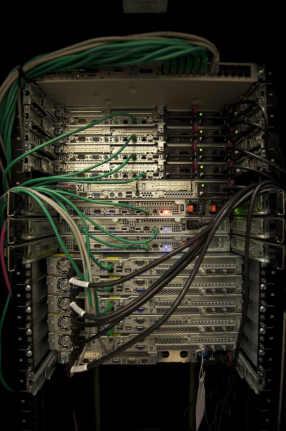
Photo · Wikimedia Commons
Core Building Blocks
DNS
Translates human-readable domain names into the IP addresses machines actually route traffic to.
Routing
Routers inspect destination addresses and forward packets hop by hop toward their target network.
Firewalls & NAT
Control which traffic is allowed through, and let many internal devices share one public IP.
DNS & DHCP Fundamentals
The two protocols that quietly configure every device on a network before it ever sends useful traffic.
Common DNS record types
| Record | Purpose |
|---|---|
| A | Hostname → IPv4 address |
| AAAA | Hostname → IPv6 address |
| CNAME | Alias one hostname to another |
| MX | Where email for the domain gets delivered |
| TXT | Free text — SPF/DKIM, domain verification |
| NS | Delegates a zone to its authoritative servers |
| PTR | Reverse lookup: IP → hostname |
The DHCP lease process (DORA)
A new device broadcasts to the whole segment: "is any DHCP server out there?"
Each server that hears it offers an available IP, lease time, gateway, and DNS servers.
The device broadcasts which offer it's accepting, so any other servers withdraw theirs.
The chosen server confirms the lease. The device configures its interface and starts talking.
Mesh VPN Architecture
A WireGuard-style mesh gives every node a direct, encrypted tunnel to every other node — no central VPN concentrator to become a bottleneck or a single point of failure. The catch is NAT: two nodes both sitting behind consumer-grade or carrier-grade NAT often can't reach each other directly at all.
The fix that holds up in practice is a dedicated relay/bastion node — one box with a real public IP that every other node can always reach. When two NAT'd peers can't punch through to each other directly, traffic hops through the relay instead. "Unreachable" becomes "one hop further," not "broken."
# /etc/wireguard/wg0.conf — a node behind restrictive NAT
[Interface]
PrivateKey = <this-node-private-key>
Address = 10.100.0.5/24
ListenPort = 51820

[Peer]
# Relay / bastion node — always reachable, bridges nodes that can't
# reach each other directly because of double-NAT / CGNAT
PublicKey = <relay-node-public-key>
Endpoint = relay.example.net:51820
AllowedIPs = 10.100.0.0/24
PersistentKeepalive = 25
PersistentKeepalive matters specifically for the NAT'd side — without it, the NAT's connection-tracking entry times out and the tunnel silently goes one-way until the NAT'd node sends traffic first.
This exact pattern runs a real multi-node fleet today — see the full Cloud Fleet & Infrastructure-as-Code case study for how it survived two nodes disappearing without warning.
Secure Multi-Site Connectivity
This is us.
VPN, CGNAT, a Core site and a physically separate offsite NAS, directory services tied over the same mesh — this is the actual architecture connecting a remote site with no public IP back to a core network, running today.
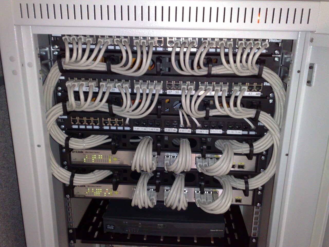
Photo · Wikimedia Commons
Three hops, broken down — each one is a decision that had to survive contact with a real network, not just a diagram.
A site on a consumer or satellite ISP connection typically sits behind Carrier-Grade NAT — it has no public IP of its own and can't receive an inbound connection no matter what's configured on its own router. Port forwarding doesn't fix this; there's no public port on the ISP's side to forward. The fix that actually holds up: the remote site dials outbound to a relay/bastion node that does have a real public IP, and every other site — including the core site — reaches it through that same always-on relay.
This generalizes past one site: any location on a consumer or satellite connection is a candidate for this exact pattern. One relay node with a public IP, reachable by every CGNAT'd site, beats chasing a different port-forwarding exception for every ISP's particular flavor of NAT.
The core site's Local NAS is the working copy — day-to-day reads and writes, lowest latency, on-site. A second, physically distinct Offsite/Remote NAS at a different location holds a synced copy, reachable over the same encrypted mesh.
The split matters for one reason: a copy that lives in the same building, on the same power circuit and the same network segment as the primary, isn't a real backup — it's a second copy of the same single point of failure. A remote copy survives an incident at the core site (fire, power loss, hardware failure, ransomware that spreads across a local network) in a way a same-site copy structurally cannot.
Directory services (LDAP) live inside the core site alongside the app/management VMs — reachable from the remote site over the same WireGuard mesh used for everything else, not through a separately exposed authentication endpoint. One encrypted path in, one thing to secure and monitor, instead of a directory server with its own public-facing listener and its own attack surface to patch and watch separately. The same peer-verification discipline from the Open-Source Enterprise Networking case study — diff every new peer's public key against its private-key file before calling it done — applies here too: a directory service is only as trustworthy as the tunnel authenticating the peers that reach it.
See the full firewall/VPN/IDS build behind this mesh in the Open-Source Enterprise Networking case study, and the hardening discipline behind it on Security & Hardening.
Sample: Nginx Reverse Proxy
TLS termination, forwarded headers so the backend sees the real client IP, and a rate-limited endpoint — the same shape used to protect this site's own contact form.
# in /etc/nginx/nginx.conf, inside the http {} block
limit_req_zone $binary_remote_addr zone=contact_form:10m rate=5r/m;

server {
    listen 443 ssl http2;
    server_name app.example.com;

    ssl_certificate     /etc/letsencrypt/live/app.example.com/fullchain.pem;
    ssl_certificate_key /etc/letsencrypt/live/app.example.com/privkey.pem;

    location / {
        proxy_pass http://127.0.0.1:8000;
        proxy_set_header Host $host;
        proxy_set_header X-Real-IP $remote_addr;
        proxy_set_header X-Forwarded-For $proxy_add_x_forwarded_for;
        proxy_set_header X-Forwarded-Proto $scheme;

        proxy_connect_timeout 5s;
        proxy_read_timeout    60s;
    }

    # Throttle one public endpoint without touching the app itself
    location /api/contact {
        limit_req zone=contact_form burst=5 nodelay;
        proxy_pass http://127.0.0.1:8000;
    }
}

server {
    listen 80;
    server_name app.example.com;
    return 301 https://$host$request_uri;
}
Subnetting Cheat-Sheet
The CIDR sizes that come up constantly in real network design.
| CIDR | Subnet Mask | Usable Hosts | Typical Use |
|---|---|---|---|
| /24 | 255.255.255.0 | 254 | Standard office/home LAN |
| /25 | 255.255.255.128 | 126 | Half a /24, split across two VLANs |
| /28 | 255.255.255.240 | 14 | Small device group / DMZ segment |
| /29 | 255.255.255.248 | 6 | Tiny link segment, a few appliances |
| /30 | 255.255.255.252 | 2 | Point-to-point link (router-to-router) |
| /32 | 255.255.255.255 | 1 (host route) | A single-host route, no subnet at all |
Rule of thumb: every bit you borrow from the host portion halves the usable addresses and doubles the number of subnets. Subtract 2 from the raw address count for the network and broadcast addresses on anything /30 or larger.
Why This Matters for Hosting
Every site on this server sits behind Nginx as a reverse proxy, with a firewall in front and rate limiting on public-facing endpoints. Solid networking fundamentals are what keep a small VM like this one both fast and safe under real traffic — see Security & Hardening for how the two connect.